A schematic diagram of the typical intermittent pneumatic compression


Exergy analysis of pressure reduction, back pressure and

Schematic diagram of a compressed air energy storage (CAES) Plant
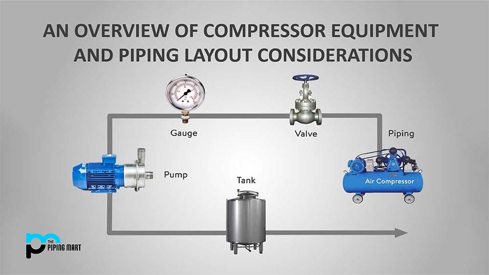
An overview of Compressor Equipment and Piping Layout

A schematic diagram of the typical intermittent pneumatic

Typical schematic diagram of the HP.

15084 PDFs Review articles in VARICOSE ULCER

Shumi Zhao's research works National Institute of Biological
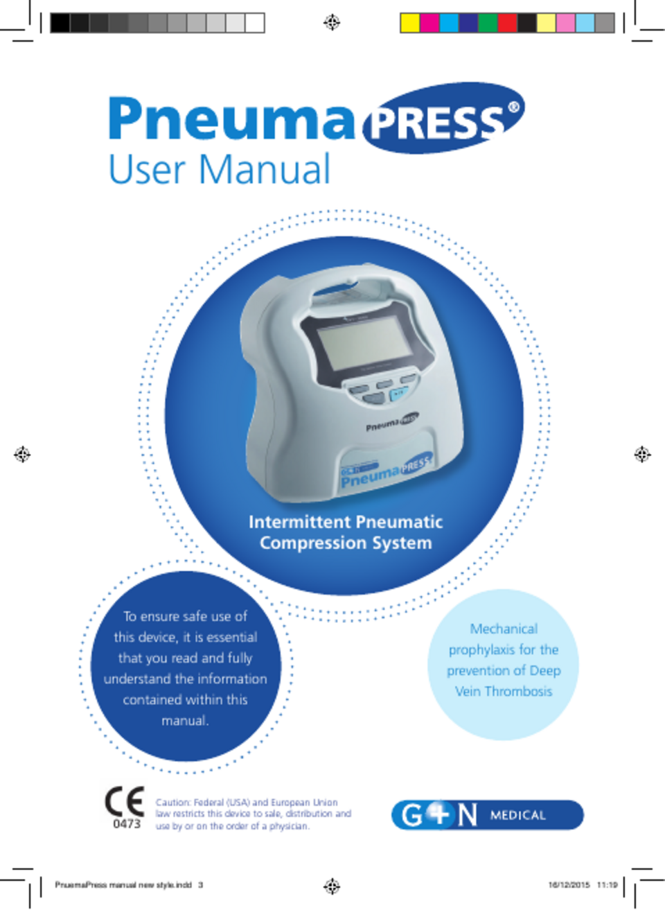
PneumaPress DVT-2600 User Manual Dec 2015 PDF download

4 Basic Pneumatic Circuits

Rong LIU, PhD

FIGURE E Schematic representation of heart valves (left) and their

The working principle of screw unit and common failure analysis

A schematic diagram of the typical intermittent pneumatic
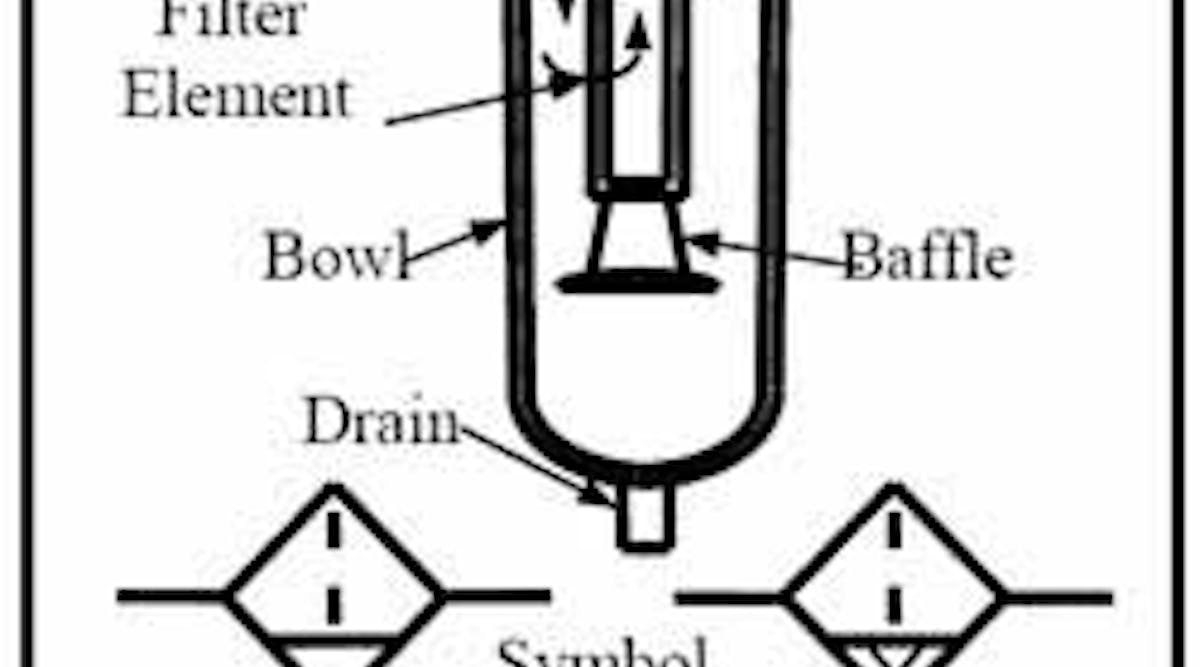
CHAPTER 7: Air and Hydraulic Filters, Air Dryers and Lubricators

Part 6 – Compressed Air Systems – PEG-3715 Refrigeration & Gas